Updated 7 October 1998
THIS IS THOR'S HAMMER GIT!
Theory Development Device to show the forces involved in inertial propulsion, developed from Joao Andrade of Brazil's original theory experiment.

Updated 7 October 1998
Pictured above is a theory development device to show the forces involved in a GIT inertial thruster. It is frankly more complicated mechanically than a GIT, however, it WILL develop a sizeable amount of inertial thrust, and will not be plagued by the high traction needs in a simple "smooth orbital" version of the GIT.
In a GIT, we have three different force profiles to examine, and, as is well known in motion physics, action and reaction forces are paired, such as a rifle kicking back against your shoulder when a bullet is propelled forward, the action and reaction pair is opposite and equal, the same force pairs that the now, soon to be extinct rockets work on!
 In a GIT we have what is known as a variable velocity circular movement of the orbitals, they speed up and slow down around the cycle, and in previous attempts at inertial propulsion, this would result in a split force profile, a balanced "tug of war" so to speak.
 As the orbital speeds up and slows down, the forces on the center of mass of your system forms two half circle thrust profiles that are refered to as tangential forces, since they are tangent to the circle (along the circle's circumference), and they form a reaction pair with the stronger centrifugal force at the high velocity end of the cycle, to cancel out any hoped for gains.
In the GIT we introduce one more motion to be considered, and that is the spin accelrations of the orbitals, and that forms a torque from the axis of the orbital (which, as we all know, produces a counter-torque on the rest of the system, our reaction to the action).
In Joao Andrade's original experiment, one we are calling the swing arm torque test (essentially a motor and gyro spin mass out on a free swinging arm, the swing axis being parallel to the spinner's axis), he energized the motor with it's gyro mass while the system was at rest, and he found that the reaction with the spin acceleration torque produced a larger radius movement of the spin mass and arm!
This is of course, conservation of angular momentum operating here (contrary to popular belief in today's scientific community, the GIT does NOT have to break any physical "laws" to operate, we just use motion geometry to get a new principle using old, well known facts!).
The swing arm test shows us that an angular acceleration, (the spin increase and decrease of the orbital), will power a TANGENTIAL motion of our orbital mass! This means we have a more linear motion powered FROM A SPIN ACCELERATION (not "linear" or forward motion relevant)!
NOW we have a way to inertial propulsion!
Since the centrifugal and tangential accelerations ordinarily pair off linearly in a tug of war, and thus cancel out as far as forward propulsion is concerned, now we add a new motion to consider, and with the spin accelerations "competing" with the centrifugal for the "affections" of the tangential accelerations, the spin powered tangential motions in effect CANCEL (linearly) a portion of the tangential forces on the main axle that ordinarily cancels the centrifugal forces!
This leaves us with a now truely unbalanced centrifugal force!
To show how this is possible, without having to deal with the horrendous slide producing forces that have made many GITs fail over the past year, I've developed an experiment that our school children can try that I call Thor's Hammer (for many reasons ;).
When done properly, will show true inertial propulsion, and then they can teach their PHD parents that have been "educated" into stupidity! (I know that's harsh, and I CERTAINLY don't want anyone to get the impression that I'm anti-education, but it seems that mud-headed ideas (contrary to Clarke's law ;) often get institutionalized as "solid knowlege" and THAT is the target of my attacks!)

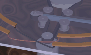 Thor's Hammer consists of a motor on an arm with a gyro mass attatched to the motor's axis, which gets it's power from wipers that contact conducting strips. The conducting strips provide reversing voltage on each side to reverse the torque accelerations of the spin mass on the motor.
The arm is propelled in a circular motion by another (main) motor, which has a simple rig in the belt drive to allow tangential accelerations of the arm so the main drive motor can spin at the same rate, while the arm speeds up and slows down.

This "stretcher" slider with idler pulleys is free floating (in a sleeve to keep it from falling, and travel stops, not shown), and will move to one side as the main motor brings the orbital arm up to maximum speed (the position shown), the orbital at the maximum centrifugal force "nose" position.
When the conduction strips are energized, the arm accelerates and decelerates from the spin reaction of the torque to tangential translation, the sliding idler carriage will move to the extremes, to allow the main motor to remain at near constant turning rate.
I haven't yet built this version, with all the folks in the world that CAN get these things built will report in, and give us dimensions, motor sizes, spinner weights, etc., and we can have a rather nice theory machine to demonstrate the principle!
Construction hints: The spinner must NOT reach maximum speed during it's travel on one side, and if the spinner does, add spin mass to your orbital motor. The tangential acceleration of the arm (arm and spin assembly advancing or retarding from the average orbit rate), will operate ONLY during a SPIN acceleration, while the spinner is speeding up or slowing down.
Of course it would be best if the spinner does NOT reach a complete stop or reverse on the reverse power side, but frankly, it should work anyway if it does. If an extendable slider is used, and different size belts put in to keep the sliding idler carriage from hitting the stops before each half cycle is complete, it will gain maximum efficiency, since your main drive motor can run at a steady rate.
With a variable voltage feed to your conduction strips, spin torque (to tangential) accelerations can be controled for determining best ratios for thrust.
 As shown, this device has the main motor moving the arm COUNTER-CLOCKWISE, the spinner is also powered up COUNTER-CLOCKWISE (on the left side of this graphic), which reacts and slows down the arm. Experimentation has shown that a counter-clockwise spin up will power the arm in a clockwise direction.
When it reaches the bottom (or tail) of the cycle, it then contacts the reversed voltage, and the arm spinner motor brakes as it becomes a generator against the applied voltage, slowing down the spinner, and it's reaction with the tangent arm actually speeds it up toward the nose on the right side!
I am hoping that "real scientists" can see how the tangential accelerations are ENTIRELY powered by a torque reaction, and as such, will not interact with linearly considered forces (forward motion impulses from our centrifugal force), and that the centrifugal forces will not be directly effected by the orbital spin motions (a spinning mass can be moved forward in space with the same force as a non-spinning one, or even an accelerating spin). Of course the tangential forces ARE effected, and as such, partially drop out of our "tug of war".
By powering our tangential motions with orbital torque, we now have a truely unbalanced centrifugal force! Remember, the tangential accelerations are NOT bearing entirely on the center of system mass (reacting with, in a momentum exchange), but are also reacting with the spinner's torque impulse, an "external mass" input.
Given that we've had troubles with rolling traction failing us in the Original GIT (though successful water and pendulum tests HAVE been severally repeated), many failures have discouraged others to not pursue this line of monumental import. This one is MUCH less likely to fail if run properly!
Overcoming mental inertia with spin inertia! (and a LOT of hard work in communications!) David Eugene Cowlishaw - 3:00 am Monday morning, 18 May 1998 - Edited 1 July 1998 DavidC (Voltage control)
Edit of 7 October 1998 - the above document section was edited to comply with the now known force dirctions that resulted from testing, I had it backwards in some of the text!
The two spinner transport arms are finger leaved and loose on the axel, allowing them to speed up and slow down when driven by the spinner's torque reactions, and the springs bounce the spacing between the arms back and forth, Allowing for a simple, single speed main arm drive!
Note: If DPDT ( Double Pole Double throw) switch is used for the decelerate side's conduction strips (motor becomes generator side), all spinners will spin up to top speed during main arm motor wind up, to allow for smooth power up, then throw the switch, the voltage will reverse on the strips, and one side begins the unbalanced acceleration motions by decelerating the spinners, but they are less likely to reach full stop spin, and throwing the switch the other stops your thrust motions! Hey, maybe even speed control could be fudged in too! Interesting eh?
I modeled it up while watching DS-9 (you know, the evil Riker steals the Defiant!), and posted it here at 11 pm Thursday night, May 21 1998 This just in! I decided to do a two fisted Molnjir! The sliding idler arm for the belt drive not required, the springs take the time shifting for a steady main axel bar turning rate!
.
Since the arms can pass between their spring restraints, now over and under the arm, instead of on either side of the arm, the arms can move more than the arc limit by the previous version's solid barriers, and thus allow higher drive ratios.
This is my next test model, and the one I am now recommending for theory testing, since it is not plagued by the horrendous traction stripping forces that the purely mechanical "smooth orbital" versions experience (no truer name was ever given, after running it for a few seconds! ;).
The smooth orbial GITs have proven to be problematic, and used by some as "proof" that the concept doesn't work. So I need to eliminate all-thumbs researchers from discouraging others! This one will work, or it will be apparent that it's broken!
I am modeling this variant this week, and hope to have it on line along with the Mars Convention pictures and my air table tests with the retreaded MarsConDemo GIT, so check back real soon! - DavidC - 12:30pm Wednesday, 9 September.
 On the right is the mechanism I described above, and though the spinners aren't mounted (nor have I drilled the holes and such to mount them and pass through the brushes for electrical contact, this is what it looks like!
The over/under drive stars are solidly mounted to the axel, and the springs drive the loosly pivoting arms. This allows for larger drive ratios (the orbital arms can travel further from their "neutral position" than the previous version, the unit shown (for proportions) is a 1/4 inch axel, and small RC motors would be mounted at the 2.5 inch radius (centered) with their spin masses. These wedges are 22.5 degrees each, so if all four were pushed together, it would make a 90 degree total grouping.
I've rendered the individual arms in slightly different colors so you can see the interleaved axel attatchments of each, this version could use only two pieces, doubled and flipped upside down for the other sides, a bit of savings in manufacturing.
Stay tuned to this page, although it may not exactly look like this, the ThorGIT variant is looking to be the best over all so far, and I will build it next. If you want to put one together first, ask me for details!
10 September 1998 - DavidC
24 September 1998
 On the right is the Thor variant now under construction, and consists of 2.5 inch broad hinges (the removable pin variety, and opened is 2.5 inches square).
The outer corners of the hinges are chopped off with an abrasive cutting wheel to allow room for the spring caps, and the hinge's "knuckles" were drilled out to 1/4 inch for an extended shaft (the 1/4 inch rod you can get at most hardware stores).
I used the second hinge in the set to make arm plates by cutting off thier loops. The hinge plate and cut plate, sandwich the motor attatchment strapping, and is needed to balance the arm equally on the shaft (the hinge pin is off center, so I flipped one upside down, and made the arms thick enough to center them equally on the axle).
Two matched 7 ounce DC motors are used for the spinners (with added hollow cylinder masses), and a much smaller motor, geared down through an O-ring belt drive, turns the main axel against friction losses. Two 45 degree wedge stops (rubber sandwiched in metal strips, and peeking outside of the metal "bread slices") run between upper and lower spring caps on both sides. This gives each arm 135 degrees of freedom with respect to the main axle.
These stops prevent "head knocking" between the spinner arms, and keep the arms from wrapping their springs around the axle, only needed to "suggest" a lowest energy shaft position, and not strong enough to prevent spring steel spagetti from happening during start up! ;)
This animation is only one half orbit, looped (watch the setscrew on the clear pulley at the top), but enough to show fairly smooth motion for a more byte-lite graphic.
I'm still awaiting the spring attatchment and travel stop caps from my local machinist, it's in the pipeline he says! I've yet to finalize the brushes that the spinners get their juice from, which also reverses the voltage to achieve our reversing spinner torque. Of course solid state current control will be engineered into commercial models, but for now, brushes are easy for me to do, and make it fairly straight forward for others to see the timing.
The color of the spinner's cylinder masses shows spin rate, red for highest spin, blue for lowest spin (at the nose), and shades of purple for the in-between acceleration "snapshots". This gives us the inverse acceleration profiles of the original GIT. During spin down, the orbit speeds up, and vice-versa, to achieve our "magic" transfer of momentum away from and back to the system's center of mass, "hiding" it as increased spin momentum on the spin masses during the rearward orbital travels.
Happilly, the parts and dimensions I chose will allow the main parts to fit snuggly into a coffee can, now there's a lot of casing work I don't have to do! If you need to see the axel attatchments and such, placements and parts not shown here, uhhhh.... I'd rather you didn't try to build this one! ;) I've caught enough grief from unskilled builders, but the mechanically inclined can ask me for details by email if needed.
Plans are to test this small version, and if it proves out the principle effectively, a larger version using car starter sized motors will be undertaken, but I need to get my machinist excited (and frankly, believing with his own eyes that it does in fact work!;), so a large utility grade (say a canoe pusher) thruster can be built for public demonstrations.
This model may very well be the "kit" planned for when a solid performer shakes out of the testing and new concepts being explored currently. I know some screws and bolts are missing, don't tell me that, this is just an animation to show movements! ;) There is an odd multicolored rod thingie under it, with a green cone to make a "that-a-way" arrow (not seen as such unfortunately), which I used to accurately match colors of the spinners with from frame to frame, and to make color reductions the same across several renderings for animation, and is not a part of the machine.
Slow going here, but steady progress for this variant is being achieved, one I'm counting on to eliminate the sorrowful performance of the smooth orbital GIT variatals, and one I think has the best chance of commercial applications, being more reliable, and easily adapted to current technical capabilities.
Stay tuned! - DavidC - Noon, Thursday the 24th 1998
 Hi again! As you can tell, this design is evolving as I have the parts made and get them fitted together, and currently the main axle caps, the spinners, actually, nearly all parts shown but the axle pulley and commutator rings are done.
The commutator rings are being cut from a 2 inch rigid copper fitting, which is 2.25 inches outside diameter, and as shown in the picture on the right, two sets of commutator split rings are combined into 4 "fat tailed T" sections with their arms wrapped around. This will allow the testing of seperate conduction sectors for the torque reaction.
The commutator set up shown has 180 degree sections (full spin acceleration on one side, full deceleration the other), and 90 degree sections shown, and by moving the ring set up 1/4 inch (the dual 3/16" thick brushes are 1/2 inch apart center to center), the electrical conduction to the spinners will only apply spin torque in 1/4 of the orbit on each side, to test whether or not the applied spin torque at those sections is more efficient.
The brush casing is from an automobile alternator (replacement parts). The business end that holds the pair of brushes is cut away from a massive attatchment arm, and will likely be attatched by an extension of the motor straps, sheet metal that will also have "ears" to attatch the springs to the arms, not shown.

Shown on the left is a cutaway of the actual spin masses, as they were built. A dremmel collet is used in a compression fitting (like used in flared copper plumbing, though these were custom cut), which grips the motor axle firmly enough to prevent it from spinning free from the shaft, yet allows easy and quick removal.
The "six gun" drilled aluminum disk that is attatching the lead antimony ring masses to the motor shaft (tire balance weight lead), with the collet and compression nut, is less than a 12th of the mass of the lead rings, the total assembly of which weighs in together at .36 pounds total, at least that's what they measure on the local Safeway checkout scales (I get LOTS of grins with odd things like that here locally! ;).
I intend to test this current version as is, but will leave enough room in the construction to add one more mechanism, one I call the SAA for "Spider Arm Accelerator", an improvement previously not released.
That improvement resulted from private discussions on how to make the failed SpiderGIT variant work, and used to mechanically accelerate and decelerate the spinner arms with an adjustable (variable from zero to maximum tangential accerations) ring cam.
In the OG (for Original GIT), the mechanical demands of the parts in motion have the orbital slowing down on one side as the spin torque wants to speed it up (and vice-versa on the other side), and testing of these spinners shows a STRONG tangential force from the ring mass spinners on their support arms as they accelerate, but IN THE OPPOSITE DIRECTION of their actual motion (for the spin direction) in the original GIT!
The "head to head" torque force components in the OG may be a needed element in transfering the linear tangential momentum to and from the spinner assembly's more linear tangential accelerations around the axle, with the inertial moment (I call the angular mass) of the spinners.
In the Thor, that characteristic is missing, and at this point, I'm being cautious about it's possible performance, since there are as yet no reports on working models of this variant.
 While the force profiles for the Thor and the OG are NOT the same, the tangential accelerations are still driven from the spin mass (moment of inertia of the spinners), an "external" mass to the linearly accounted for machine part masses and motions.
Just a quick update for you folks, lots to do yet, so, less chat, more construction! It is coming together, and with the addition of the SAA, ALL of the force profiles of the original GIT can be reproduced, all independently of one another, including reversed relationships, and simple voltage control will allow extremes of each acceleration element to be tried in combination.
I've yet to model the SAA for the current construction, but here's an old sketch of one for a four armed version, to convey the idea, and establish publication priority ;)
8 pm, Wednesday, 7 October 1998 - DavidC
* INDEX *.
.